First, you need a Neutron or X-ray source.
X-ray sources are typically laboratory generators, often used for crystallography, but also include large accelerators called Synchrotrons. Neutron sources are typically Research Reactors, and even the weakest reactor such as the famous Triga teaching reactor, produce many more neutrons than a radioactive source, or even a laboratory D-D or D-T accelerator.
Large Spallation Neutron Sources compete with reactors, and our cameras work well with them even when they are pulsed sources. Our cameras work best with the thermal neutrons needed for nuclear reactions, where their energy is reduced to 25 meV-1 eV by collisions with light atoms. A thermal neutron with a temperature of 290K (0C) has an energy of 25 meV and a wavelength of 1.8Å (0.00018µ) according to Gabriel Cuello's ILL calculator.
Why buy a camera instead of making one ?
It is of course possible for a big laboratory to make their own neutron cameras. But even the largest laboratories find it convenient to buy such equipment. Although the principles of neutron imaging are simple, there are many details that can only be learned by experience. Frankly it's faster and cheaper to simply buy such basic equipment rather than re-invent it. With experience it might be modified in-house to serve a particular need, but why not start with an off-the-shelf product that is already used by many others to kick-start research you can use to justify further funding ?
Advantages of NeutronOptics Cameras
NeutronOptics cameras are competitive with the best imaging cameras found in big laboratories, but are less expensive because as a small company established in 2007 we have lower overheads and less administration. Technical advantages of our cameras include:
leading neutron imaging labs. The detector can be off-centered to reduce camera depth.
the lens, or the scintillator extension to change the optical path length.
of the camera box, can be easily shielded, and use air assisted Peltier cooling.
and the camera would be much more complicated, requiring water cooling.
amplified 10m extensions up to 30m total.
The origins of neutron cameras
Neutron cameras are almost as old as neutron diffraction itself, and are simply a variation of
the even older photographic techniques used from the discovery of X-rays. Indeed neutron cameras are
just X-ray cameras with a component (usually LiF) to convert neutrons
into ionising particles and X-rays, which are then converted into light using an X-ray scintillator (usually ZnS).
The neutron Polaroid film camera was invented by Harold Smith at ORNL in 1961, and was used with a hand painted 6LiF/ZnS scintillator from the beginning of ILL in the early 1970's. The film recorded the shadow cast on the scintillator by a semi-transparent object in a beam from a neutron or x-ray generator.
The idea of using a video camera instead of film goes back to Arndt, U.W. & Ambrose, B.K. (1968) in Cambridge (UK) "An Image Intensifier – Television System for the Direct Recording of X-ray Diffraction Patterns", IEEE. Trans. Nucl. Sci. NS-15, 92-94. This was also proposed for neutron detection by Arndt, U.W. & Gilmore, D.J. (1975) "A Neutron Television Camera Detector", Brookhaven Symposia in Biology, 27. VIII 16.-VIII 23.
Neutron CCD cameras were then developed at ILL and elsewhere for tomography and other imaging applications. They consisted of the usual neutron scintillator screen reflected in a mirror and imaged by a sensitive lens and camera. An attempt was made by A. Heidemann in the 1990's to replace the ILL Polaroid neutron camera by a CCD camera based on the AUDINE Project. This proved too large for routine use, but a cheaper compact version (pp 85-86) developed by A. Hewat in 2006 was widely adopted.
How can an inexpensive Neutron Camera compete ?
The principles of the neutron or x-ray camera are described by the PSI laboratory of the Swiss ETH, who are important collaborators and clients of NeutronOptics.
 Neutron intensities are low and neutrons are difficult to detect because they are non-ionising.
They do however interact with the nuclei of atoms, and nuclear fission and decay
can produce ionising particles that can easily be detected. This is the basis of all neutron detectors,
using neutron absorbing nuclei such as 3He, 6Li, Gd...
Neutron intensities are low and neutrons are difficult to detect because they are non-ionising.
They do however interact with the nuclei of atoms, and nuclear fission and decay
can produce ionising particles that can easily be detected. This is the basis of all neutron detectors,
using neutron absorbing nuclei such as 3He, 6Li, Gd...
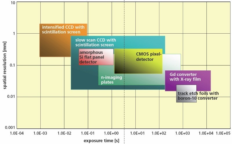
(This table is from a PSI brochure).
CCD and CMOS cameras cover most neutron imaging needs (click to enlarge).
However, position sensitive neutron detectors are usually expensive. Expensive neutron cameras typically use a large CCD or CMOS chip, perhaps coupled to a photomultiplier or micro-channel plate using a tapered optic-fibre bundle. Clearly such hardware is expensive, so is there a cheaper solution ? The answer is Yes, for many applications.
If very fast acquisition is essential, Photon or Electron Multipliers do produce brighter images, but usually with more noise and lower dynamic range. Tapered fibre bundles increase the effective area of the chip, but unless the Field-of-View (FOV) is very small, you still need a lens to image it onto that larger area. You can eliminate the optics with flat panel or "pixel" detectors, but these are eventually damaged by the direct beam. Indeed, CCD and CMOS cameras still cover most neutron imaging needs for large area high resolution detectors in large laboratories (PSI figure above).
We will attempt only to indicate some of the issues without going into detail.![]()
Although thermal neutron energies are low (~0.025eV), the energy released by prompt fission following neutron capture by nuclei such as 6Li is high (4.79MeV).
6Li + 1n -> 3H + 4He + 4.79 MeV
The resulting fission products produce as many as 160,000 light photons when absorbed by a scintillator such as ZnS. NeutronOptics cameras use the same 6LiF/ZnS neutron scintillators from SCINTACOR and RC-Tritec as much more expensive cameras. The ZnS is doped to emit green light, where our CCD and CMOS cameras are most efficient.
LiF/ZnS neutron scintillators are opaque, but a transparent Li-glass scintillator produces only about 8,ooo photons per absorbed neutron, so is often used with a photo-multiplier as in an Anger camera. Glass scintillators are also only available for relatively small areas.
6LiF/ZnS neutron scintillators contain less 6Li than natural lithium (6.5% atomic weight).
For example, our thickest 450µ NDg scintillator weighs 100 mg/cm2. Since the ZnS:6LiF mass ratio is 4:1, then 1 cm2 contains no more than 20 mg of 6LiF, and multiplying by the ratio of the atomic weights of 6Li and F (6/19) we obtain 6.3 mg/cm2 of 6Li. So our 100 mg/cm2 scintillator mixture contains at most 6.3% weight of 6Li, less than the 6.5% in natural lithium. In fact it will be less than 6.3%, since some of the mass is due to the plastic binder.
The efficiency of a scintillator increases with its thickness, but resolution decreases. Ordinary neutron cameras with 400µ SCINTACOR scintillators have a resolution of ~100µ, and it is difficult to obtain much better than 50µ even with thin RC-TriTec LiF/ZnS scintillators. With high flux sources 10-20µ Gd2O2S:Tb(6LiF) scintillators can achieve <20µ resolution, while very thin 157Gd2O2S:Tb films can be used for resolution down to 5µ, but light output is very much lower than from ZnS.
The capture efficiency of 6Li and Gd decreases rapidly with increasing energy, and imaging with fast neutrons is difficult even with a relatively thick scintillator, which reduces resolution. Fast neutron scintillators are typically 2-3mm thick slabs of Poly-propylene/ZnS (PP/ZnS), where the ionising particles are knock-on protons rather than 6Li fission products. Fast neutron scintillators are also commercially available, but are still much less efficient than thermal neutron scintillators, with lower resolution.
X-rays are converted to visible photons by scintillators containing heavy metal oxides. Much work has been done to increase scintillator efficiency and minimise radiation exposure for medical examinations, so NeutronOptics uses the most sensitive CAWO (Agfa-Gevaert) OG2 scintillators for our x-ray cameras, with resolution of ~100µ (5 lp/mm). Light channeling in columnar CsI(Tl) allows scintillators to be thicker, and up to 16 lp/mm can be obtained with high efficiency using columnar CsI scintillators. 20µ thick Gd2O2S:Tb powder or YAG:Ce single crystals can do even better (with longer exposures}.
1mm aluminium windows are transparent for neutrons, but for x-rays we use 0.5mm carbon fibre windows, with an estimated transmission of >70% even for soft CuKα X-rays (8 KeV). Under some conditions, the woven texture of the double-layer carbon fibre window can be seen faintly. If necessary, it can be eliminated using a flat-field correction, which can be done with imageJ using the Image Calculator Plus plugin, or as part of tomographic reconstruction. Some image acquisition programs have an option to perform dark and flat field corrections in real time. Special CAWO OG2 scintillators have a thin black coating that largely eliminates the need for a cover window., and columnar CsI(Tl) scintillators can also have an opaque amorphous carbon coating (but are then more fragile).
The resolution of a optical system is historically measured in line-pairs/mm (lp/mm or lpmm) where a line-pair is a black line followed by an equal white line. Think instead of lines/mm, where each line is separated by an equal space. We use wire grids, with a 50µ grid (500 mesh) having ~25µ wires enclosing ~25µ holes, corresponding to 1000/50=20 lp/mm. Otherwise the Siemens Star is a popular x-ray and neutron resolution target. Resolutuion is sometimes quoted in microns, refering to the size of the pixels in the image, but that number has to be at least doubled to obtain the spacing between points that can be resolved. Effective optical resolution also depends on the contrast of the system, or Modulation Transfer Function. There are other definitions of resolution and ways of measuring it, for example by imaging a straight edge, but for practical purposes we simply use our wire grids.
The resolution of consumer cameras has increased dramatically, driven by marketing and consumer demand - at the cost of poor efficiency in low light. But the resolution of a neutron or x-ray camera depends mainly on the resolution of the scintillator (see above). This normally decreases with thickness, since light is emitted along the capture path. Since the efficiency of a scintillator increases with thickness, there is a compromise between resolution and efficiency. Neutron resolution is ultimately limited by the collimation of the neutron beam, and neutron intensity decreases with collimation.
For x-ray imaging, geometric magnification from an x-ray point source can increase effective resolution; with collimated neutron sources, that is almost impossible. Intensity is also less of a problem for x-ray sources.
Neutron beam intensity, even from high flux reactors, is very much lower than x-ray beams from ordinary lab generators. We recommend at least 104n/cm2/s thermal neutrons for neutron imaging. If the scintillator resolution is typically 100µ (0.01cm) then that equates to 1 n/s collected on the pixel area of 10-4cm2, which will produce images in a few seconds. This near single neutron detection is only possible because of the large number of photons produces by the neutron fission fragments. Further photon, or electron, multiplaction in the detector is possible, and we have experimented with an Electron-Multiplying CCD (EMCCD), but decided not to pursue it for imaging because it also reduces the dynamic range.
Even a small 100kW-1MW Triga reactor found in some Universities is suitable for large area neutron radiography without photon or electron multiplication. But radioactive neutron sources, or even "table-top" neutron generators, may not produce enough intensity. These sources produce fast neutrons, which must usually be moderated to thermal energies, and even if the generator is quoted at 109 n/s fast neutrons, this must be divided by 4πr. Then the moderator at distance r cm diffuses thermal neutrons with intensity falling also as 4πR.
These factors rapidly multiply, so the resulting n/cm2/s flux of thermal neutrons on the scintillator is generally smaller than from even the smallest reactor, requiring long exposures. Radiography is possible, but perhaps not tomography. With radioactive sources producing only perhaps 105 n/s fast neutrons, even radiography becomes a "tour de force".
The efficiency with which photons are collected depends on the ratio of the effective area of the detector chip, enlarged perhaps by an optic fibre bundle, to the area of the scintillator screen. So smaller screens or larger chips have an advantage; a 1/2" chip is twice as efficient as a common 1/3" chip. Light gathering power also depends on the f-number of the lens i.e. the ratio of the focal length of the lens to its diameter. Common SLR camera lenses start at f1.4 or more, but since efficiency depends on solid angle, our small camera f1.0 lens is twice as efficient.
Large detector chips and large aperture lenses become expensive, and an SLR lens also implies a large camera such as our advanced imaging camera. Small NeutronOptics cameras use smaller chips up to 1", so a smaller C-mount lens can be used, but still large enough to allow f1.0. The focal length of a small lens can be reduced to 8mm or less, making for a very compact camera. The depth of focus of a large aperture lens is also small, but only the plane of the scintillator need be in focus.
For advanced imaging we use large lenses such as the Nikkor 50mm f/1.2 and modern 35mm f/0.95 Micro-4/3 lenses. Since the lens-detector distance can be easily adjusted in our advanced camera, this lens can image either a large 250x200mm FOV at full camera extension, or a smaller FOV with higher intensity without the extension. Since a standard F- or micro-4/3 mount is used, the lens can be readily exchanged to obtain a different FOV.
Consumer digital cameras often use CMOS sensors, but CCDs are suited to very long exposures (>60s) because they have lower background noise (dark current), especially when they are cooled. We also read out our CCDs slowly (>1s) to minimise readout noise. CMOS detectors are improving rapidly, and have much faster readout with low noise. They are now recommended for all but the longest exposures.
Consumer cameras use colour CCDs, with filters covering three pixels at each point. Light is absorbed by the filters and less light is collected by smaller pixels. Ordinary cameras use "mega-pixel" chips, which are good for resolution, but bad for efficiency because the pixels are tiny. Our high efficiency monochrome detectors have no filters and a relatively small number of large pixels to maximise light gathering.
In our "interline" CCDs, charge accumulated by photo-sensitive columns is quickly transferred to adjacent storage columns. The advantage is that smearing is avoided during readout, so a mechanical shutter is not needed. Some of the chip area is used for storage, but that is compensated by the use of micro-lenses over every pixel, which also maximises light gathering from low f-number lenses, which deliver light at low incident angles. HAD (Hole Accumulation Diode) CCDs use an extra accumulation layer to drain-off thermally generated electrons and reduce thermal noise, most important at low light levels. Our back illuminated CMOS detectors have a very high quantum efficiency.
An EMCCD or "electron multiplying" CCD increases the electronic gain such that "single photon" detection becomes possible. Electron multiplication can be compared to photon multiplication with Micro-Channel Plates (MCPs), but photon multiplication is not needed for most neutron imaging where so many photons are produced for each captured neutron. We can supply EMCCD cameras but simply multiplying the gain does not of course impove neutron counting statistics, and usually reduces the dynamic range.
Finally, resolution is mainly limited by neutron beam collimation and the thickness of the scintillator, and it is a disadvantage to have a high resolution chip with correspondingly small pixels, as in consumer digital cameras. A Kodak report explains When digital cameras need large pixels.
A dynamic range of up to 16-bits is provided by our digital cameras, but the effective dynamic range is the ratio of Fullwell capacity to Readout noise, and is always lower than the 16-bit (65,536) readout. Dynamic Range in Decibels (DR)= 20log (Fullwell capacity/Readout noise)dB eg typically DR= 10,000= 80dB. Note that electron- or photon-multiplied cameras, and CMOS cameras, generally have a lower dynamic range, and the dynamic range of our 8-bit video camera is only DR= 256= 48dB. A high dynamic range means that contrast between slightly different intensities is better, important for imaging.
![]()
NeutronOptics cameras use an electronic shutter that allows long exposures, with charge integration in-camera to reduce random electronic noise. Exposures can be several seconds, or even minutes with Peltier cooling. For simple neutron beam alignment it can be convenient to output a standard video signal that can be displayed on an ordinary TV monitor. Our original video camera scanned the integrated CCD image at PAL video rates of 25 frames/second, though the image itself is integrated over n-frames, e.g. with n=250 for a 10 second exposure. Our recent cameras output a digital signal over an amplified USB-2/3 cable that can be up to 30m long, and generally have much faster readout times.
All our cameras are supplied with free software that will run on even the smallest Windows PCs. It will run on even a tablet with only 2GB of memory and simple SSD storage, such as the Lenovo MiiX 310, but more recent mini-PCs or tablets or even a mini PC stick might be used. MacIntosh software is also available for many of our cameras. Amplified USB2 cables of up to 30m provide both power, control and image acquisition with our small cameras.
Integration with Linux control systems and GigE networks can best be achieved by using SSH and Linux Remote Desktop to control such a mini-computer server running the camera. With our larger Atik imaging cameras you can use Atik Air to control the camera using a simple server, such as a Raspberry Pi, over WiFi or Ethernet to the client PC. You can even control the camera with a
stand-alone Raspberry Pi, without the need for a PC (but even a simple PC gives you additional advantages, and is not much more expensive). Some of our simple cameras can be provided with a native GigE interface.
Summing up the NeutronOptics Camera Design
NeutronOptics cameras are inexpensive, compact, have good efficiency and resolution, and are very easy to
use and eventually repair; essentially they are "plug and play". The compact NeutronOptics alignment camera produces images with 10s exposures at 104.n.cm-2.sec-1,
or only 1 neutron/second per 100µ resolution pixel.
Where higher sensitivity or dynamic range are needed, such as for very low flux sources or tomography, NeutronOptics offers advanced imaging cameras that are still quite inexpensive, based on bright f/0.95 APS-C lenses and large inexpensive CMOS detectors.