If you have the 2CCD Laue camera, you need these instructions instead.
If you have the high resolution CCD option, you need these instructions instead.
If you have the Slim CCD camera, you need these instructions instead.
If you have the FLIR CMOS camera, you need these instructions instead.
If you have the Macro camera, you need these instructions instead.
If you have a standard video camera, you need these instructions instead.
These instructions are for Windows-10; for other versions they may be slightly different.
Orienting Crystals with the 1-CCD Laue Camera
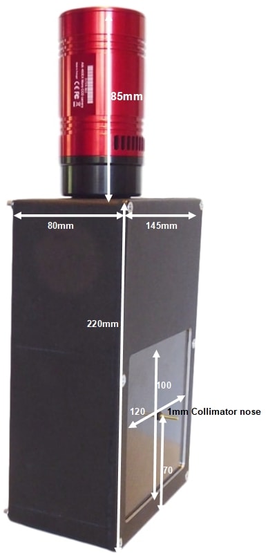
To control this hi-res CCD, use either the native Artemis Capture application (which can be downloaded with the Atik core software), the ImageJ imaging environment, the LabView graphical instrument control environment, or the Artemis SDK using MS Visual Basic, C++.The photo shows the 120x100mm camera, but a compact 100x80mm camera in a 200x120x67.5mm thick box is also available at the same price.
- Sensor Type: Sony ICX825ALA or ICX694ALG
- Image size: Diagonal 11mm (Type 2/3") or 16mm (type 1")
- Resolution: 1392x1040 or 2759 x 2200
- Pixel Size: 6.45x6.45 µM or 4.54 x 4.54 µM
- Binning: from 2x2 to 8x8 (improved intensity and read-out )
- High sensitivity: (QE>75% at 500-600nm), low smear
- Low dark current: 0.003@-10 °C, excellent anti-blooming
- Full well capacity: 20,000 or 40,000 electrons
- ADC: 16 bit grey scale image, optional filtering & distortion
- Readout Noise: 4 e- typical (slower readout = less noise)
- Readout Time: 1-3s
- Interface: USB 2.0 High Speed with 10-20m USB cables
- Power: 12v DC 0.8A, to EU, UK, US/Japan, AU/CN standards
- Maximum Exposure Length: Unlimited
- Minimum Exposure Length: 1/1000s (1s at full resolution)
- Cooling: Thermoelectric set point with max ΔT=-27°C
- SDK: C++, VB Wrapper, .net Wrapper, ImageJ, LabView
Backscattered Laue with the 1-CCD Laue Camera
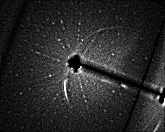
A Si backscattered Laue pattern was obtained by Dr Dean Hudek at Brown University, and a Sm2Fe17 pattern was obtained by Dr Léopold Diop and Prof W. Donner at the Technische Universität Darmstadt in only 2 minutes on a 1960's Philips generator (click to enlarge).
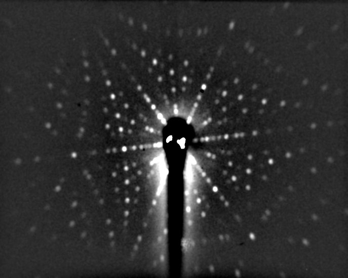
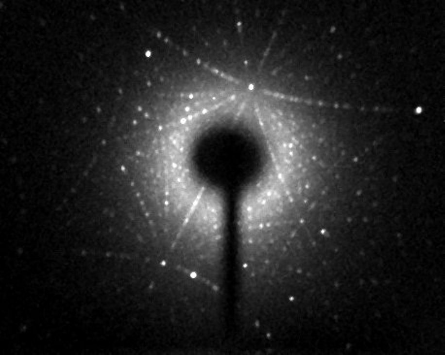
a) Si (Dean Hudek, Brown University USA). b) Sm2Fe17 (Léopold Diop T.U. Darmstadt)
Setting up the NeutronOptics 1-CCD Laue Camera
The photos below show how Prof. W. Donner and Dr L. Diop at the T.U. Darmstadt converted a Huber Image Plate Laue camera (left) to use the 1-CCD Laue camera (right).
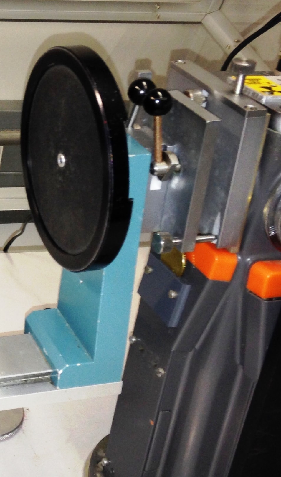

Left photo: The Huber IP camera is the circular disk mounted on a blue support on a guide rail. The collimator is locked and the beam shutter opened with the two black knobbed levers on the double-metal plates that form the Huber-800 alignment mechanism, which is mounted on a Philips X-ray generator with a spot size of ~1mm at 30-50 kV and 30-50 mA. The screw at the top, and two at the bottom, adjust the height and tilt of the collimator.
Right photo: The Huber-800 unit is retained, together with the blue camera support, when the Huber IP camera is replaced by the 1-CCD camera. An additional support bolt on the rail under the bottom left supports the heavier camera. The new collimator is aligned in the Huber-800 mechanism for maximum intensity, and the camera is then bolted on using an aluminium plate and four M4 bolts.
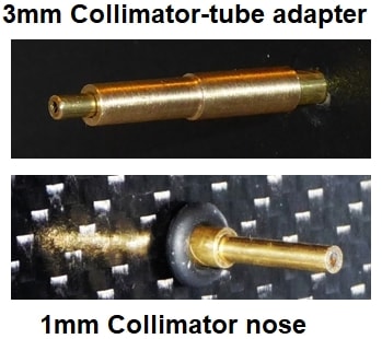 Mount the camera as close to the source as possible using the 4mm bolt holes at the back; minor adjustments to position and orientation are necessary. Before inserting the 1mm collimator tube into the camera, check that it fits the source exit and allows no x-ray leakage. You will need to make a small adapter (top left) to take the 3mm collimator tube, depending on your source. The 1mm collimator slides into the 3mm tube (bottom left), with the nose extending toward the crystal ~30mm from the window.
The camera and collimator must be precisely aligned, and the source voltage and current set for maximum x-ray intensity through the collimator. Our mini i-Cam camera could be used to align the beam and position the sample, otherwise use the Laue camera itself to check beam transmission. The carbon fibre window and scintillator are not fragile.
Typical exposure times for backscattered Laue are ~300 seconds. But first try a shorter exposure with no beam to check that everything is working - you should see background noise. You can also try forward scattered Laue, where exposure times are much shorter.
Binning is important for faster exposures with backscattered Laue, since very high resolution is not needed. Typically binning of 4x4 increases efficiency by a factor of x16 ! ![]()
Installing the Driver and Artemis Capture software
- Browse the CD & launch "SetupArtemisUniversal.exe" or "artemisinstaller.exe"
- Install the driver & "Artemis Infinity" and "ArtemisCapture" to control the camera
- You can also download and pre-install the Artemis core software & drivers
- Plug the 12V supply into the camera; the fan should start up
- Connect the 10m USB extension to the computer, wait for its driver to be installed
- Then connect the camera to this cable, or directly to a USB port on your computer
- The computer should automatically search for and install the driver. Be patient !
- The Windows Device Manager should now show an ArtemisCCD USB controller
- Launch "Artemis Infinity" or "Artemis Capture" to control the camera (next section)
- Read the manual for the HiRes camera for more details and troubleshooting
Artemis Capture for long exposures in backscattering
Launch Artemis Capture and "View" Exposure, Display & Cooler. The "File" menu is used to save images, the "Camera" menu to connect the camera, and the "Colour" menu should be set to "Raw". The camera icons launch a single exposure or continuous loop exposures. "Tracker", "Marker" and "Filter" icons are not used.IMPORTANT: Zoom out to see the green outline of the full CCD.

- Set exposure time 300 (s) with BinX=4 and BinY=X for 4x4 binning and Dly(s)=0 delay
- Check the "Auto stretch" option to select the best 8-bits out of the 16-bits. Note that
- "Zoom" (or the wheel mouse button) zooms the display window
- Set the temperature to -10
- If the CCD is cold, click "Warm up" and wait a few minutes before disconnecting
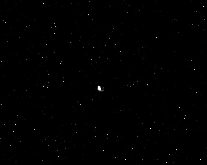
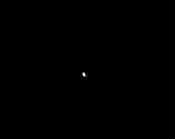
The isolated bright pixels can be filtered out with ImageJ's "Process/Noise/Despeckle" menu, which replaces the bright pixels by the average of their surroundings (right hand image). This will not filter out Laue diffraction spots, which are much broader. The central spot due to light leakage is not a practical problem, since it co-incides with the incident beam. If necessary, it can be eliminated with a very little black paint under the collimator O-ring. Be careful not to allow paint to run through onto the scintillator, which is immediatedly behinder the carbon fibre window. Or you can simply turn off the room lights when collecting x-ray images.
Emphasizing the Laue Pattern with imageJ
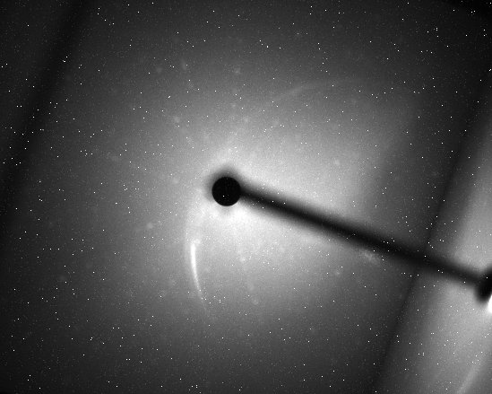
You can use ImageJ's "Process/Noise/Despeckle" to filter out electronic noise and "Process/Subtract Background" with "rolling ball radius 25-50 to remove some of the diffuse backround. You might also try ImageJ's "Process/FFT/Bandpass filter" to filter out large structures of 30+ pixels and small structures of 3+ pixels, with "autoscale" and "saturate" to emphasise the peaks.A more powerful macro routine can be downloaded to ImageJ\macros\toolsets then loaded by clicking on the red ">>" menu item on the far right and selecting "Subtract Diffuse Bkgd". This will install the command "Plugins/Macros/Subtract Diffuse Bkgd". The left image below shows a very poor image with isolated bright pixels and no obvious Laue pattern. The right image shows the astonishing effect of this macro command. This organic material showed strong diffuse scattering; hopefully your patterns will be better, but it is surprising that even very noisy images can yield useful patterns. This "median filtering" macro was provided by M. Cammer as an alternative to "Process/FFT/Bandpass filter". (click image to expand).
Hints on getting Optimal Performance
- Use a Windows-7 or -10 computer with 2GByte of memory eg an Intel NUC
- If necessary, close other applications and windows that may use memory
- Try a short exposure to check that it works before starting a long exposure
- Check the files that are created in your image directory
- Note that the ImageJ lens distortion correction is not perfect far from the centre
- The CCD can be cooled to reduce noisy pixels. You can also use ImageJ filters
- Fogging may occur if you cool below zero (the CCD chamber contains a desiccant)
- The desiccant can be replaced by removing the large screw on the camera shaft
- Try unplugging and re-plugging the USB cable
- Try re-booting your Windows computer :-)
- The center of the image doesn't correspond to the centre of the window
because the CCD chip is not centred to better than 0.5mm in its housing
Indexing and orienting the Laue pattern
The interactive Laue pattern generator DiffractOgram is a Java applet that displays the Laue pattern for a given crystallographic cell. You can spin the crystal around to find the orientation that best matches your pattern. A number of more advanced Laue indexing applications are freely available. The Cologne Laue Indexing Program (CLIP) is one of the best, along with the QLaue Indexing Program. Older applications such as OrientExpress and the ambitious new ESMERALDA Laue suite might also be tried.You can download these instructions as a PDF file.